Design Guidelines for 3D Printing
Simple and easy rules for designing well and getting the best out for your 3D project!
Index
2. MAXIMUM DIMENSIONS, GENERAL TOLERANCES and MATERIAL INFILL
4. MINIMUM THICKNESS AND THIN WALLS
5. HOLES, CHANNELS, GAPS AND UNDERCUTS
6. TEXTS, LOGOS and OTHER FEATURES
9. PARTS WITH LARGE AND THIN SURFACES (MJF/MSLA PRINTING)
10. OUR TIPS ON POLYPROPYLENE (PP)
1. ACCEPTED FILES FORMAT
-
STL, STEP, STP
-
only files containing SINGLE parts, except chained parts (Chapter 4) and multi-part caged parts (Chapter 8)
2. MAXIMUM DIMENSIONS, GENERAL TOLERANCES and MATERIAL INFILL
❗All tolerances listed are to be applied to the entire component, including specific areas such as thicknesses, holes, pivots, centre distances, etc
| Material | Max. Dim. | Tolerance | Infill |
| Nylon PA12 (MJF) | 380x284x380 mm (15×11.2×15 in) | ± 0.3mm, ± 0.3% dimensions >100mm | 100% |
| Nylon PA12 Glass Beads 40% (MJF) | 380x284x380 mm (15×11.2×15 in) |
± 0.4mm, ± 0.4% dimensions >100mm |
100% |
|
Nylon PA12 White (MJF) Nylon PA11 (MJF) TPU (MJF) |
380x284x380 mm (15×11.2×15 in) | ± 0.5mm, ± 0.5% dimensions >100mm | 100% |
|
Polypropylene PP (MJF) |
250x250x250 mm (9.8×9.8×9.8 in) |
± 0.6mm, ± 0.6% dimensions >100mm | 100% |
| FDM Materials | 300x300x400 mm (11.8x11.8x15.7in) |
± 0.6mm, ± 0.75% dimensions >100mm |
30% |
| MSLA Resin Materials with LSPC | 274x155x400 mm (10.8x6.1x15.7in) |
± 0.3mm, ± 0.3% dimensions >100mm | 100% |
Attention: Walls with a thickness greater than 15mm may suffer deformations outside the stated tolerance range. The amount of material in the section and its thickness directly influence thermal stresses and shrinkage.
In order to avoid this problem, it is recommended to empty massive areas of the part or to build honeycomb lightening structures.
You can also consult this page for information!
The Top Black dye, which is available among our Finishes (MJF), does not increase the final dimensions of the parts, as it is produced by an impregnation process.
Any RAL coatings chosen from the available Finishes (MJF) will lead to a dimensional increase in thickness for approximately the following values:
Gloss Paintings: 100 microns (0.1 mm)
Matt Paintings: 80 microns (0.08mm)
Metallic Paintings (Gold and Silver): 100 microns (0.1 mm)
Soft Touch Black Painting: 200 microns (0.2mm)
3. INPUTS and GAMES
For advice on the design of connections, gaps and interlocking parts, please consult the dedicated section, which you can find here!
4. MINIMUM THICKNESS AND THIN WALLS
- MJF e MSLA
- FDM
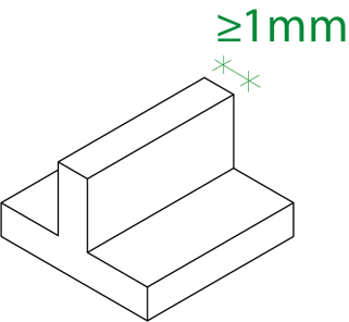
MJF and MSLA technologies can handle very thin walls, but to be sure of receiving parts of an adequate quality, walls must be at least 1mm thick.
Some parts with the protruding profile on the main geometry may present the same risk, despite compliance with the minimum thickness.
Reinforcing these parts may help to maintain the integrity of the component.
For FDM technology, the minimum guaranteed thickness is at least 3mm.
Areas below the minimum guaranteed thicknesses are generally printable, however, perfect realisation is not guaranteed. This is due to the not entirely predictable behaviour of these thicknesses during both printing and transport.
⚠️ The presence of walls below the minimum guaranteed dimension can sometimes lead to the file being rejected during the technical validation process.
Compliance is the responsibility of the customer, or the designer of the file, so we cannot guarantee the integrity of areas even if the part has passed validation.
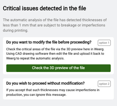
When setting up your quote on the Quotation page, if the file you load contains a part with areas of less than our minimum guaranteed thickness, you will be notified with the message "Critical issues detected in the file".
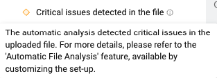
To check the areas involved, you can preview the file and then flag the "Visualizza pareti sottili" option; any critical areas due to thickness will be shown in red, and you can choose whether to proceed with the uploaded file or modify the geometry before completing the purchase.
![]()
Would you like your file to be verified by an expert? Click here to find out more!
When setting up your order from the Quotation Tool, if you upload an object with areas of less than the minimum guaranteed thickness, you can choose how to proceed between these two options:
5. HOLES, CHANNELS, GAPS AND UNDERCUTS
The 3D printing technologies we supply, MJF, MSLA and FDM, do not allow for the complete cleaning of areas such as holes, cavities, channels, gaps and undercuts when these do not provide sufficient access for cleaning; the risk is that these will be plugged by dust, backing filament or printing resin, not guaranteeing complete removal of excess material.
💡Here are some tips for designing your file:
MJF and MSLA: The minimum recommended diameter or opening is 1mm; if the hole depth is three times the diameter, cleaning won't be guaranteed.
❗For blind holes, we suggest adding service holes to allow removal of construction dust; through holes instead of blind holes can facilitate this.
MSLA and FDM: internal cavities or gaps unreachable by removal tools may have leftover support structures.
It is the responsibility of the customer, or the designer of the 3D file, to comply with the instructions given here.
In case of doubt, please take into consideration the "File check" option that you can directly request in the configuration phase before completing your order.
![]()
6. TEXTS, LOGOS and OTHER FEATURES
MJF and MSLA: we recommend the design of texts, logos and other features with hollow characters, with heights and thicknesses of at least 1mm, in order to ensure efficient cleaning from dust or excess resin. For embossed solutions we similarly recommend keeping 1mm as minimum height and spacing between characters to avoid breakage during processing
FDM: for both hollow and embossed texts, we recommend maintaining at least 2mm in character width and thickness (see image below).![]()
It is the responsibility of the customer, or the designer of the 3D file, to comply with the instructions given here.
In case of doubt, please take into consideration the "File check" option that you can directly request in the configuration phase before completing your order.
![]()
7. MASSIVE PARTS and VOIDS
For parts printed by MJF and MSLA technologies with a very massive area, these run the risk of deforming or bursting with small bubbles on the surface due to the thermal shocks that occur during the printing process.
To prevent this problem, we suggest that you draw at least 2 holes of 8mm diameter on your file to allow the building powder to exit.
In addition, as indicated on this page, we recommend that you do not print solid parts with thicknesses of more than 15mm, but empty them leaving walls of 3-4mm.
Walls greater than 15mm will be automatically emptied by our technicians during pre-printing.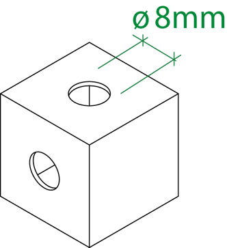
For Metal Replacement- FDM materials, we suggest component thicknesses of less than 5-6mm to avoid deformation due to thermal shrinkage of the material.
Compliance with this characteristic is the responsibility of the customer, so we cannot guarantee the cleaning of these areas even if the party has passed validation.
8. MULTIPART FILES
Printing multipart files is normally not recommended as this does not guarantee complete control of the printing and finishing process of the parts.
If for FDM and MSLA printing any multi-part files will always be rejected and refunded, for MJF printing technology we can give you some design cautions to keep in mind when designing and ordering, so that your uploaded files will be accepted by the technicians.
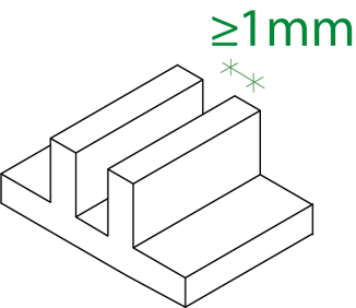
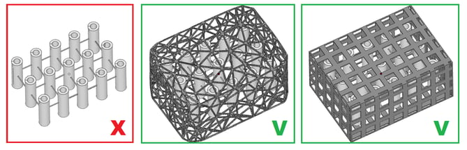
You can upload a multi-part file containing equal or different parts of small dimensions (maximum 35*35*35mm for each part), as long as these have a containment cage around them, as suggested in the green boxes: in this way small parts won't be lost or misplaced during cleaning operations.
Multipart files that only have connections between them (as in the red box) will no longer be accepted in order to avoid loss or breakage.
The containment cage must be at least 1mm thick and have sufficient mesh to prevent the smallest parts from escaping.
Also be sure to adequately separate the parts from each other and the cage by at least 3mm.
The parts will be supplied in the cage itself as drawn and are subject to the instructions presented on this page.
❗For obvious reasons, it won't be possible to guarantee proper cleaning, quality control, and possible painting among the available Finishes.
9. PARTS WITH LARGE AND THIN SURFACES (MJF/MSLA PRINTING)
Due to technological limitations, parts with large, thin, planar surfaces are subject to thermoplastic deformation (warpage phenomenon).
For this reason, we suggest that you do not design thin, large parts, such as an A5 sheet or larger: the thermal stresses involved in the production process could easily manifest themselves in thermoplastic deformation, causing the part to be curved or twisted.
This can also occur on parts of great thickness or density (>3cm) with at least one of its dimensions extending more than 15cm.
What is our advice? For parts with such features, we can give you some advice that can limit but not completely eliminate the risk of deformation.
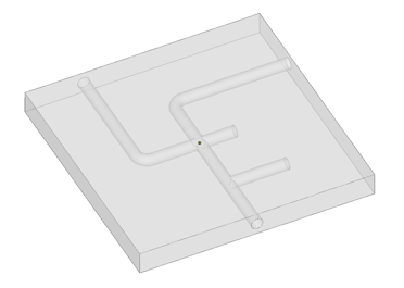
We suggest that you make the area on the opposite side of the exposed part in unloaded form, emptying almost completely the thickness that would otherwise be full, modelling ribs (one-way or crossed) or a reticular, honeycomb or rib reinforcement structure.
In this way, the possible occurrence of warpage on parts moulded with MJF and MSLA technology is partially reduced, while at the same time giving greater flexibility and lightness to the part as well as an obvious cost saving due to the reduction in actual moulded volume.
❗Any warpage on printed parts cannot be refunded or returned as this is a technological limitation that cannot be foreseen and guaranteed.
10. OUR TIPS ON POLYPROPYLENE (PP)
-
The volume/total area ratio between these two values may not exceed 4-5 times.
If this value exceeds this, the printing may be unstable and any dimensional problems cannot be predicted.
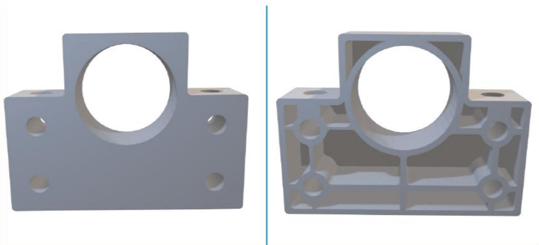
Furthermore, we suggest you lighten the densest areas of the part by modelling pockets or grooves and add a possible honeycomb reinforcement structure or ribs, as you can see in the image below.
-
Polypropylene is a material with a particular printing behaviour. For this reason, we recommend you choose this material for your project especially if you need to exploit its chemical or electrical properties.
💡Take a look at the material page to find out more!
-
To obtain the best possible result from your Polypropylene printing, we recommend limiting the size to 100x100x100mm.
-
We suggest that you maintain a constant thickness over the entire surface of the piece. This will help the material behave uniformly during the entire printing and cooling process, limiting any deformation caused by differential thermal stresses.
-
In order to receive a part with holes and gaps totally free of printing powder, model diameters greater than 3-4mm on your file.
Partial or total occlusion of the holes on smaller diameters may occur as a technological limitation of the material itself.


