How do I apply threads and tolerances of holes and shafts?
To indicate threads, you do not need to draw them on your 3D file: just follow this simple guide!
By uploading an STP/STEP file for CNC machining in the Quotation Tool, you can indicate the threads and tolerances to be machined by entering them manually from the online system.
How to draw threads and tolerances for CNC
Due to the absence of unified criteria for defining threads between the different CAD packages, it is not necessary to draw threads in your program: it will be sufficient to draw holes with the correct ISO diameter of the desired thread (a simple cylindrical shape is enough), e.g. 4.2mm for an M5.
➡️ Download the Threads Table and the Tolerances Table with the dimensions of the preholes and shafts compatible with our standards: Metric, Metric Fine, Helicoil Gas/Withworth, UNC and UNF.
These will help you design your model and correctly indicate the threads to the Quotation Tool!
❗Please note that:
-
Blind hole threads are generally made up to a maximum of 3/4 of the hole depth.
-
If through-hole threads are too deep, they will be made half each side, except where indicated otherwise in the notes field or by agreement with an expert.
How to indicate threads and tolerances in the Quotation Tool
Following is a short guide on how to indicate threads and tolerances in the online system.
1. First of all, you need to upload the file to the Quotation Tool and select a material available for CNC machining (discover all the materials for machining here).
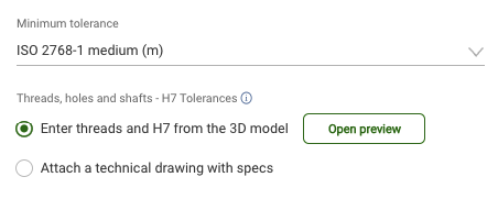
2. At the bottom of the Configurator page you will see a box to enter any holes or shafts ("Threads and tolerances of Holes and Shafts"). Once the box is clicked, it will be possible to open the preview and assign compatible machining for holes and shafts detected by the system.
3. Selecting a single table row will highlight the respective hole in the preview on the left:
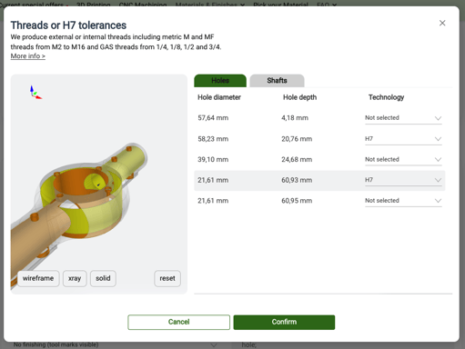
4. Holes and shafts are automatically identified by the Quotation Tool and will show only the compatible machining based on the diameter.
How to indicate threads and tolerances by forwarding a 2D table
If your model needs threads or tolerances that are not available on the website, or you simply prefer to forward us the 2D drawing of your project, it is possible.
Within the dedicated section of the Quotation Tool, check the corresponding box and attach the file in PDF format ("Attach a technical drawing with specs").

❗Any requests for non-standard threads will be evaluated upon request at the time of the quote, after evaluation of the PDF table and possible mail exchange.


