Design guidelines for CNC machining
Few and simple rules to design the best and get the most out of your 3D design.
- FILE FORMAT.
Files containing SINGLE parts in .STEP / .STP format are accepted.
Files can be uploaded within the Quotation Tool to proceed with the definition of machining specifications.
- MINIMUM AND MAXIMUM DIMENSIONS
-
Minimum dimensions: 6x6x6mm (0.23x0.23x0.23 in)
-
Maximum dimensions: 460X460X400mm (18x18x15.7 in), but may vary depending on the material; check here for the specific dimensional limits of the material you wish to use.
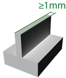
- WALL THICKNESS
The nominal thickness of the part must be greater than 1mm.
We advise you to be careful with details smaller than 1mm, as they may not hold up during machining.
- TOLERANCES.
The standard applied by Weerg is 2768-1 fine (f) and medium (m) classes.
We have created an in-depth guide for you to consult, click here!
- PDF TABLES.
PDF tables can be provided to facilitate quick reference of project specs and tolerances.
However, in the event of inconsistencies and ambiguities between the specifications in the PDF table and those in the 3D model, we will refer to the latter as the definitive source.
- FONTS AND LOGOS
If you are interested in applying fonts and logos, please follow the tips below.
Minimum width 1mm and maximum depth 1mm: click here for a list of fonts, many of them free of charge and specially created for the CNC machining. Fonts and logos with a size smaller than the above will be engraved.![]()
We recommend using Sans Serif fonts >20 points and >5mm in height.
Moneysaver: making Sans Serif fonts is on average 9 times cheaper than making Serif fonts!
Moreover, engraved fonts are much less expensive than embossed fonts.
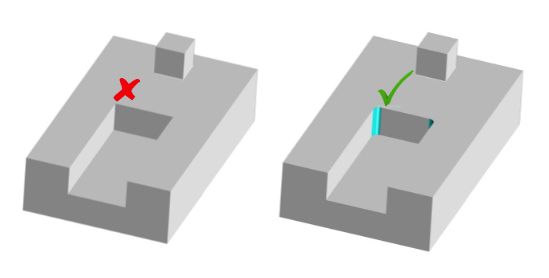
- GORGES, POCKETS AND RADII
We recommend r= 1mm minimum and 3 times less than the height (d)
Moneysaver: 1mm radius is about 7 times more expensive than a 4mm radius!
If these radii are not present in the uploaded file, the order will be suspended and a technician will contact you asking you to make the necessary changes.
It is possible that they will be applied automatically by our team of experts if it is a small one.
- IEXTERNAL THREADS AND THREADED HOLES
Threads are free and holes that can be threaded are automatically identified by the Online Tool.
Due to the absence of unified criteria between the various CAD packages for defining threads, it is not necessary to enter modelled threads on the 3D file: it is sufficient to draw the holes (a simple cylindrical shape) with the correct ISO diameter for the desired thread, e.g. 4.2mm for an M5.
Blind hole threads are realised up to a maximum of 3/4 of the hole depth.
External threads can be executed up to a maximum of 2 mm from the lower end of the cylinder.
We suggest a minimum height of 2 mm for the discharge groove to allow for the correct fit of a counterpart.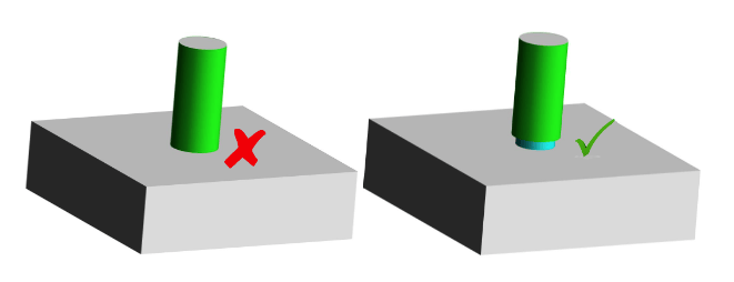
![]() Pay attention to:
Pay attention to:
- Undercut surfaces
- Sharp edges between surfaces with radius of curvature.
For out-of-parameter requests, an extra cost may be charged during the technical analysis.
For ad hoc quotes, please contact us at our email info@weerg.com
Following these simple rules will make it much easier for you to get great results.
If in doubt, do not hesitate to contact us!


