The epicyclic gear train, also known as a planetary gear train, is a compact transmission that enables high reduction ratios, significant torque and configurations that are difficult to achieve with an ordinary gear train. It is used in automatic transmissions, industrial reduction gears, geared motors, winches, the hubs of electric bicycles and in robotics.
The design process requires analysing the motion of the planet gears, calculating the transmission ratios, distributing the loads and selecting appropriate materials and production processes. This guide sets out the operating principles, the calculations and the geometric constraints, through to production by means of 3D printing and CNC machining.
What is an epicyclic gear train
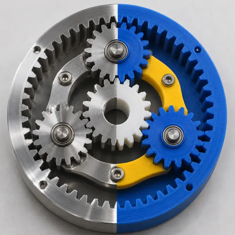
An epicyclic gear train is a gear system in which the planet gears rotate about their own axis while orbiting a central axis. Unlike ordinary gear trains, in which the axes are fixed, at least one axis moves relative to the structure.
The main advantages are:
- compactness: high reduction ratios within limited dimensions;
- coaxiality: the possibility of arranging input and output on the same axis;
- load distribution: torque shared across several planet gears, generally three;
- high torque density: the ability to transmit high torque in a small space;
- versatility: different ratios depending on which element is locked, with the possibility of combining two motions.
The components of an epicyclic gear train
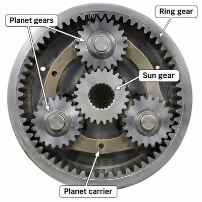
A simple epicyclic gear train comprises four components.
The sun gear
The sun gear is located at the centre of the system. It has external teeth, meshes with the planet gears and is often the input element.
The planet gears
The planet gears mesh with the sun gear and with the ring gear. They rotate about their own axis while the planet carrier guides them around the sun gear. There are generally three, arranged at 120° to distribute the loads, but the number varies according to the design.
The ring gear
The ring gear is the outer gear with internal teeth that meshes with the planet gears. It can be fixed, or it can act as the input or the output.
The planet carrier
The planet carrier supports the axes of the planet gears and determines their revolution. It is often the output element.
With a single input, one of the three main elements (sun gear, ring gear or planet carrier) must be held fixed in order to obtain a defined transmission ratio between the other two. The locked element determines that ratio.
The transmission ratio: Willis’s formula
The presence of moving axes makes the calculation of the ratio more involved than for an ordinary gear train. Willis’s formula allows the system to be analysed by treating the planet carrier as notionally stationary.
The base ratio (gear train made ordinary)
The transmission ratio of the gear train made ordinary (τ₀) corresponds to the ratio between the angular velocities of the ring gear and the sun gear with the planet carrier locked. For a simple gear train:
τ₀ = − z_sun / z_ring
where z_sun and z_ring indicate the respective numbers of teeth. The negative sign expresses the opposite direction of rotation of the two elements.
Willis’s relation
Willis’s formula links the angular velocities of the three main elements:
(ω_ring − ω_carrier) / (ω_sun − ω_carrier) = τ₀
where ω indicates the angular velocity of each element. Setting the velocity of one element to zero yields the ratio between the other two.
The Three Main Cases
Depending on which element is locked, the same gear train provides different ratios.
- Fixed ring gear (the most common configuration in reduction gears): ring gear locked (ω_ring = 0), sun gear as input and planet carrier as output. The reduction ratio is:
i = ω_sun / ω_carrier = 1 + z_ring / z_sun
With 72 teeth on the ring gear and 24 on the sun gear, the ratio is 1 + 72/24 = 4:1.
- Fixed sun gear: sun gear locked (ω_sun = 0), ring gear as input and planet carrier as output. The reduction ratio is:
i = ω_ring / ω_carrier = 1 + z_sun / z_ring
With the same 24 teeth on the sun gear and 72 on the ring gear, the ratio is 1 + 24/72 ≈ 1.33:1.
- Fixed planet carrier: the system behaves like an ordinary gear train, with a ratio τ₀ between the ring gear and the sun gear.
The following table summarises the three configurations, with the numerical example of z_sun = 24 and z_ring = 72:
| Case |
Locked element |
Input |
Output |
Transmission ratio i |
Example (z_sun = 24, z_ring = 72) |
| Fixed ring gear |
Ring gear |
Sun gear |
Planet carrier |
i = 1 + z_ring / z_sun |
4:1 |
| Fixed sun gear |
Sun gear |
Ring gear |
Planet carrier |
i = 1 + z_sun / z_ring |
1.33:1 |
| Fixed planet carrier |
Planet carrier |
Ring gear or sun gear |
Sun gear or ring gear |
τ₀ = − z_sun / z_ring |
−0.33 (ordinary gear train) |
Table 1 — Transmission ratios in the three operating cases of the same gear train.
By locking different elements, different ratios are obtained with the same gears. This is the principle used in automatic transmissions, which employ clutches and brakes to select the gears.
The geometric assembly constraint
For the planet gears to mesh correctly with the sun gear and the ring gear, the following relation must hold:
z_ring = z_sun + 2 × z_planet
To arrange the planet gears equidistantly, the sum of the teeth of the sun gear and the ring gear must be divisible by the number of planet gears. Both constraints must be checked at the design stage.
The gear design parameters
Once the ratio has been defined, the gears must be dimensioned according to the following parameters:
- module (m): the characteristic dimension of the tooth, the same for all meshing gears; it affects dimensions and strength;
- number of teeth (z): defined for the sun gear, planet gears and ring gear in compliance with the geometric constraints;
- pressure angle: generally 20°, it influences the tooth profile and the forces transmitted;
- face width: together with the module, it contributes to determining the load capacity;
- centre distance: the distance between the axis of the sun gear and that of each planet gear;
- backlash: necessary to ensure operation and to compensate for tolerances, especially in 3D-printed components.
Checks on the bending strength of the teeth and on the surface fatigue of the flanks can be carried out in accordance with the ISO 6336 standards for metal gears and VDI 2736 for plastic gears, by means of calculations or dedicated software.
The materials for an epicyclic gear train
The choice of materials depends on torque, speed, required service life and operating conditions.
Plastic gears
For low- to medium-torque gear trains that call for light weight, low noise and low friction, various technical polymers can be used:
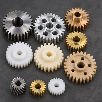
- POM-C (polyacetal): suited to precision CNC-machined gears thanks to its dimensional stability, low friction and wear resistance;
- Nylon 6 + MoS₂: a CNC-machinable polyamide with self-lubricating properties, suited to gears and components subject to friction and wear;
- PA12 and PA11 (MJF 3D printing): suited to functional prototypes and small batches, with good mechanical and fatigue strength, especially in PA11;
- PEEK: a high-performance technical polymer, CNC-machinable, for applications involving high temperatures, mechanical stresses and chemically aggressive environments.
Plastic gears offer light weight and quiet operation, but generally have a lower load capacity and thermal resistance than metals.
Metal Gears
For high-torque gear trains, sustained speeds or those subject to heavy loads, CNC-machined metal alloys are predominantly used:
- C45 steel: for gears and mechanical components requiring good strength and machinability;
- 39NiCrMo3 quenched and tempered steel: for gears subject to high stresses and cyclic loads;
- 18NiCrMo5 case-hardening steel: for gears requiring high surface hardness and a tough core after heat treatment;
- 6082 and 7075 aluminium: for planet carriers and lightweight structural components, with greater mechanical strength in 7075;
- CuSn12 bronze: for components subject to friction and wear, including gear wheels in specific applications;
- OT58 brass: for small gears and mechanisms with light loads, thanks to its good machinability.
Producing an epicyclic gear train with 3D printing and CNC
The components can be produced with 3D printing or CNC machining, according to the function and the performance required.
Prototyping and series production with 3D printing
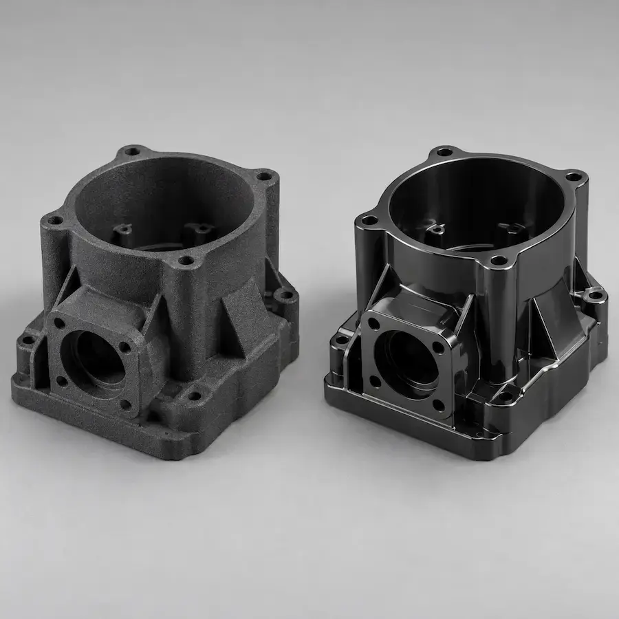
MJF 3D printing in PA12 or PA11 nylon is suited to functional prototypes and the series production of the sun gear, planet gears, ring gear and planet carrier. It allows the ratio, the assembly, the meshing and the operation to be checked before final production.
The geometric freedom makes it possible to produce the planet carrier, even a complex one, as a single piece, while the speed of production facilitates design iterations. A backlash compatible with the tolerances of the MJF process must be allowed for.
Precision production with CNC
For high-precision gears, or those subject to high torque, CNC machining makes it possible to achieve appropriate geometries and tolerances. POM is used for precision plastic applications, and quenched and tempered or case-hardening steels for the more heavily stressed metal ones.
The planet carrier, too, is often CNC-machined, in aluminium or steel, to ensure precision in the seats for the planet gear axes and in the bearing supports.
Conclusion
An epicyclic gear train combines compactness, coaxiality and the ability to transmit torque, but it requires attention to the kinematics, the geometric constraints and the dimensioning of the components. Willis’s formula makes it possible to calculate the ratios in the various configurations.
3D printing speeds up prototyping and functional checks, while CNC machining makes it possible to produce final components with the required tolerances. Using the two technologies in combination makes the transition from design to production more efficient.
Are you designing an epicyclic gear train or its components?
Upload your file and get a quote
Frequently Asked Questions About Epicyclic Gear Trains

 Weerg staff: Nov 11, 2026