8 min read
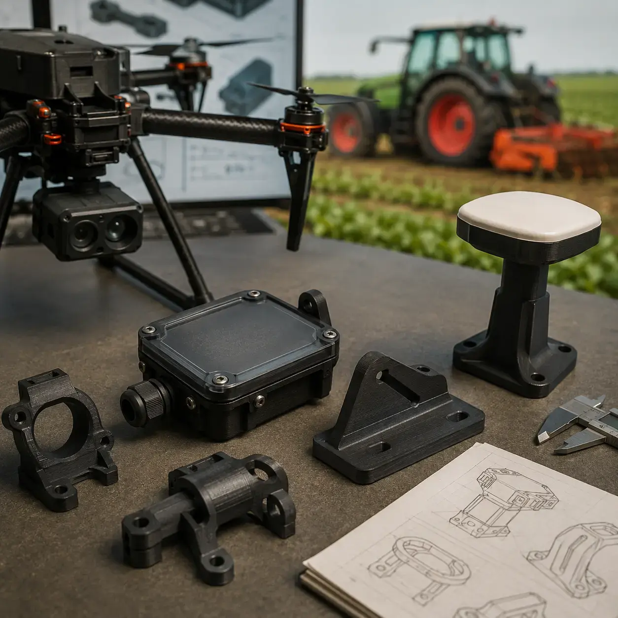
Components for Agritech: parts for agricultural machines and systems
Precision agriculture is today one of the fastest-growing segments in the civil sector. Multispectral drones, IoT control units installed in fields,...
7 min read
![]() Weerg staff
:
Apr 28, 2026
Weerg staff
:
Apr 28, 2026
If you are an engineer tasked with choosing between SLA and FDM, avoid comparisons based on opinions. This guide is founded on concrete data: tolerances measured to the micrometre, impermeability tests carried out by a university laboratory, and the use of these technologies by Ford in the development of the new electric Explorer. A definitive answer, free of marketing.
Surface finish is often the first deciding factor in the choice between SLA and FDM — and the difference is structural, not aesthetic.
FDM printing (Fused Deposition Modelling) deposits melted thermoplastic layer by layer through a nozzle. Each layer is 120–200 µm thick and the junction lines are physically visible and tactilely perceptible on any surface.
SLA (Stereolithography) uses a light source — laser, DLP projector, or LED with LCD masking screen — to polymerise liquid resin one layer at a time. The result: surfaces comparable to injection-moulded parts, with a measurable surface roughness Ra in the order of 1–3 µm, compared to the 10–30 µm typical of FDM.
In terms of geometric detail, the difference is even more marked. The Formlabs Form 4 allows embossed details down to 0.1 mm and engraved details down to 0.15 mm. Professional FDM printers, on the other hand, achieve approximately 0.6 mm in width and 2 mm in minimum height to render a feature visible — performance up to six times lower.
This difference has immediate practical consequences: semi-transparent FDM components never achieve true optical transparency, as the layer deposition lines refract light. Conversely, SLA components in transparent resin can achieve optical transmittance suitable for microfluidics applications, LED covers, and medical devices.
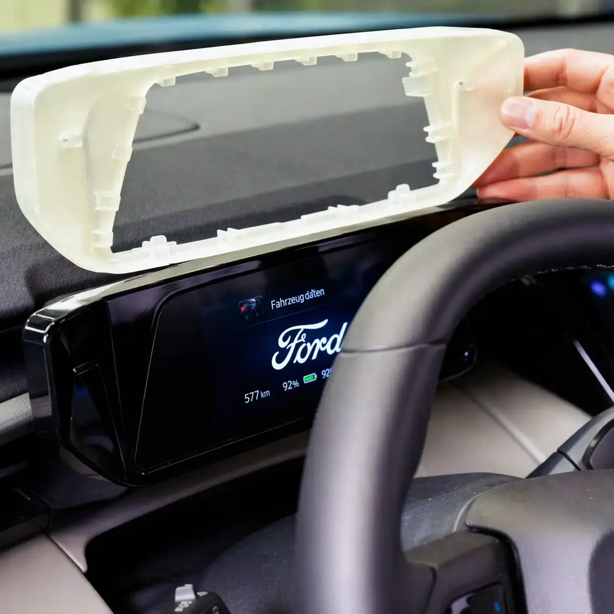
As Bruno Alves, additive manufacturing expert and tooling specialist at Ford, stated:
"The Form 3L allows us to print large parts, such as the external body panels of the vehicle. 3D printing is suited to this application because it is fast and allows us to achieve excellent quality compared to mass production."

The Underwater Robotics and Imaging Laboratory (URIL) at the University of Rhode Island conducted a rigorous study on 3D-printed housings using three technologies — FDM, SLA, and SLS — subjecting them to progressive pressurisation in an underwater chamber.
Protocol: housings for robotic components printed using the three technologies, placed in a pressurisation chamber with controlled increments. The measurement: time before infiltration and maximum pressure sustained.
Results:
The physical reason is decisive in understanding why this result cannot be replicated simply by optimising an FDM print. In SLA, the part in its raw state — the so-called green state — retains groups that are still polymerisable which, during subsequent UV curing, generate covalent bonds between layers. At the molecular level, there is therefore no real distinction between the XY plane and the Z axis: the component behaves as a single continuous polymer network.
In FDM, on the other hand, structural inter-filament voids remain, due to the very principle of thermoplastic deposition: the extruded material begins to solidify before fully bonding to the layer beneath. For this reason, these discontinuities cannot be entirely eliminated even by adjusting the print parameters.
The practical consequence is clear: if the project requires electronic housings, sealed containers, components in contact with fluids, or parts intended for humid environments, SLA represents, among desktop technologies, the only truly reliable choice. In these cases, FDM does not show a print quality limitation, but an intrinsic physical limitation of the process.
Dimensional tolerances are the most important data for anyone designing functional parts. The values that follow are measured on professional desktop and bench-top printers: Form 4 for SLA, Bambu Lab P1S as a professional consumer FDM reference, Fuse 1+ 30W for SLS.
Tolerances and design rules table
| Parameter | FDM | SLA (Form 4) | SLS (Fuse 1+ 30W) |
|---|---|---|---|
| Minimum wall thickness (with and without supports) | 0.8 mm | 0.2 mm | 0.3 mm (horiz.) / 0.6 mm (vert.) |
| Minimum vertical cylinder diameter | 3.0 mm | 0.3 mm (h=7 mm) | 0.8 mm |
| Min. embossed detail (width) | 0.6 mm | 0.1 mm | 0.15–0.35 mm |
| Min. engraved detail (width) | 0.6 mm | 0.15 mm | 0.1–0.3 mm |
| Dimensional accuracy 1–30 mm | ±0.3–0.5% | ±0.15% (min ±0.02 mm) | ±0.2–0.3% |
| Dimensional accuracy 31–80 mm | ±0.3–0.5% | ±0.2% (min ±0.06 mm) | ±0.2–0.3% |
| Dimensional accuracy 81–150 mm | ±0.5% | ±0.3% (min ±0.15 mm) | ±0.3% |
| Isotropy | Anisotropic | Highly isotropic | Predominantly isotropic |
| Surface finish | Rough / visible layer lines | Smooth / injection-like | Granular (improvable with post-treatment) |
In a test conducted on three printers with Grey Resin V5 at 100 µm layer height, the Form 4 achieved an accuracy such that over 99% of the printed surface remained within a deviation of 100 µm from the original CAD model. The data was verified by means of 3D scanning and analysis via chromatic deviation map.
Isotropy — the ability of a material to have the same mechanical properties in all directions — is a requirement often hidden in technical specifications. It is ignored until a part breaks in the wrong place.
FDM parts consist of thermoplastic material filaments deposited by extrusion. Adhesion between layers occurs through partial fusion of the contact surfaces, but this process inevitably generates microscopic voids between filaments. This results in marked mechanical anisotropy: strength along the Z axis — i.e. perpendicular to the layers — can be 30 to 50% lower than that on the XY plane.
For jigs, fixing systems, and components subject to multidirectional loads, this is a well-documented design limitation that cannot be eliminated simply by optimising print parameters.
During final curing, the photopolymerised resin forms a continuous three-dimensional polymer network. Consequently, there is no true mechanical interface between layers: covalent bonds extend homogeneously in all directions. This translates into more predictable and reproducible mechanical properties, regardless of print orientation — a decisive advantage for robotic gripping elements, sensor housings, medical components, and more generally for all applications subject to variable loads.
Ford's Merkenich facility in Cologne represents Ford Motor Company's European development centre and was the first Ford plant in Europe to adopt an SLA 3D printer, back in 1994. Today it operates a fleet of systems including the Form 2, Form 3L, and, among the world's first beta testers, the Form 4.
In the Ford Explorer project — the first Ford electric vehicle intended for the European market — the team used SLA printing to validate the design of external and internal components, including the wing mirror cap. In particular, the Form 3L allowed full-scale parts to be produced in a single piece, with a level of finish adequate even for final design reviews.
For the charging port cover — a complex mechanical assembly with moving parts — the team chose SLS printing, using the Fuse 1+ 30W with PA 12 Nylon. The decision depended on two factors: on one hand, the need to produce geometries difficult to achieve through milling or injection moulding for a limited number of samples; on the other, the requirement to carry out physical tests on the behaviour of the mechanisms.
The economic benefit was concrete and measurable: thanks to in-house additive manufacturing, the time to produce injection moulding inserts was reduced from the 2–3 months typical of outsourcing to just 2–3 weeks. As Sandro Piroddi, supervisor of Ford's Rapid Technology Centre, stated:
"If we did not have additive manufacturing available at this moment, we would not be able to face the competition, nor to be this fast."

SLA is not the right answer for every application. A serious technical guide must acknowledge this.
Use SLA when:
Consider FDM or SLS when:
The practical rule is simple: if the part must look, behave, and be tested like the final component, the choice falls on SLA or SLS. If, on the other hand, a volumetric mock-up is needed primarily to verify dimensions, FDM is generally sufficient and more cost-effective, especially for large parts.
Every day of delay has a cost: incorrect tolerances, prototypes to redo, decisions postponed.
Upload your STL or STEP file now and discover the Weerg price for SLA printing — with a 50% discount valid until 10 May 2026.
Upload the file and discover the –50% price in real time
No registration required. Quote in under 30 seconds. Delivery in 3 working days.
The differences between SLA and FDM in terms of dimensional tolerances are marked and directly affect the precision achievable in prototypes and functional components.
SLA (stereolithography)
FDM (fused deposition modelling)
In summary, for components with features below 0.5 mm or requiring critical tolerances below ±0.1 mm, SLA is in practice the only viable desktop technology. FDM remains adequate for larger geometries with less stringent precision requirements.
Use SLA printing when the function of the part requires performance that FDM cannot reliably guarantee:
Conversely, FDM remains a sensible choice when large dimensions, low costs, and non-critical tolerances are the primary considerations. In these cases, the lower precision and intrinsic process limitations are acceptable given the economic and scale advantages.
Yes, SLA printing is suitable for the production of end-use parts, provided the correct resin is selected according to the application requirements. Advanced formulations are now available covering a wide range of technical needs:
Thanks to these characteristics, many companies use SLA not only for prototyping, but also for final production in small and medium volumes, typically between 10 and 1,000 parts. Applications range from dentistry to aerospace, especially where precision, high surface finish, and specific functional properties are required.
8 min read
Precision agriculture is today one of the fastest-growing segments in the civil sector. Multispectral drones, IoT control units installed in fields,...
7 min read
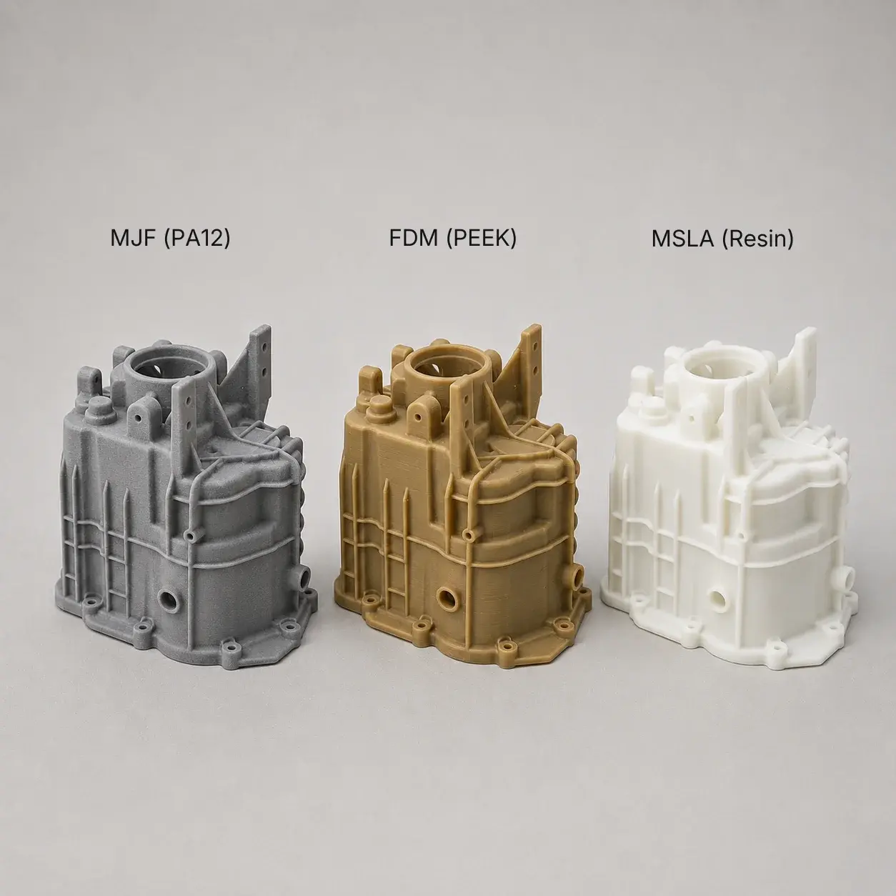
MJF, FDM or resin? It's the first question anyone with a 3D file to produce asks themselves. Each technology offers different performance, materials,...
7 min read
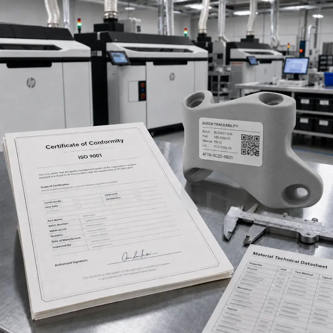
For a quality manager in the medtech sector, choosing a 3D printing supplier isn't simply a technical assessment, but a decision linked to risk...