4 min read
Composite Materials: Types, Properties and Applications
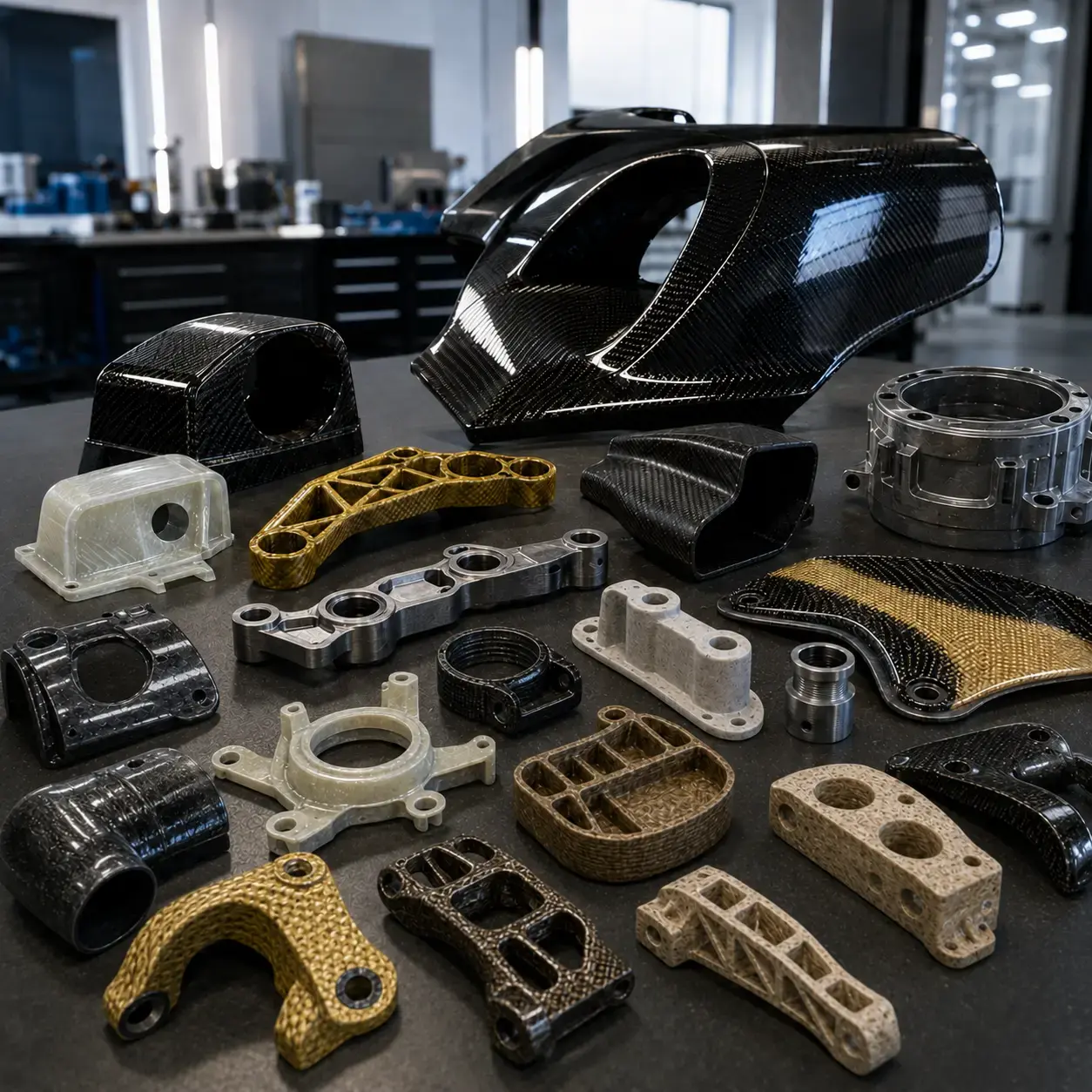
Composite materials represent one of the most significant innovations in modern engineering. Thanks to their ability to combine lightness, strength ...
The mechanical orientation of materials is a critical factor in the design of components for 3D printing and CNC machining. The distinction between isotropic vs anisotropic behaviour directly affects structural performance, reliability and costs.
An isotropic material is one whose mechanical properties remain constant regardless of the direction of the applied load. Strength, stiffness, and deformation remain unchanged along the X, Y and Z axes.
Operational advantages:
Simplified structural calculations
Predictable performance
Uniform safety factors
Independence from load orientation
Common examples of isotropic materials:
An anisotropic material shows significant variations in its properties depending on the direction of the load. Strength ratios may range from 1:0.3 to 1:0.8 depending on the process.
Key characteristics:
Complex stiffness matrix
Direction-dependent strength
Requirement for tensorial analysis
Potential for weight/performance optimisation
Examples of anisotropic materials:
Fibre-reinforced composites (CFRP, GFRP)
Layered FDM parts
Natural materials (wood, bamboo)

Higher surface resolution
More uniform mechanical properties
Properties comparable to bulk parts
Excellent compromise for additive manufacturing
Advantages of CNC machining:
Preservation of original material properties
High dimensional accuracy (±0.05–0.1 mm)
Controlled surface finish (Ra 0.8–3.2 µm)
Excellent process repeatability
Optimal materials:
Aluminium 6061-T6 → machinability and lightweight
C45 steel → versatility and cost-efficiency
PEEK → thermal and chemical resistance
Multi-axial loads:
Isotropic materials = uniform safety and simplified calculations
Von Mises analysis applicable
Directional loads:
Anisotropic materials = optimised weight/performance
Possible weight reduction 20–40%
Development costs:
Isotropic → standard design, simple testing
Anisotropic → advanced FEM, full characterisation
Production costs:
CNC → hourly costs but guaranteed precision
3D printing → cost based on volume, complex geometries feasible
Series → break-even typically 50–100 units
Automotive → isotropic engine mounts, ABS-CF covers, aluminium tooling
Medical/Dental → titanium prostheses, 316L surgical tools, biocompatible resin models
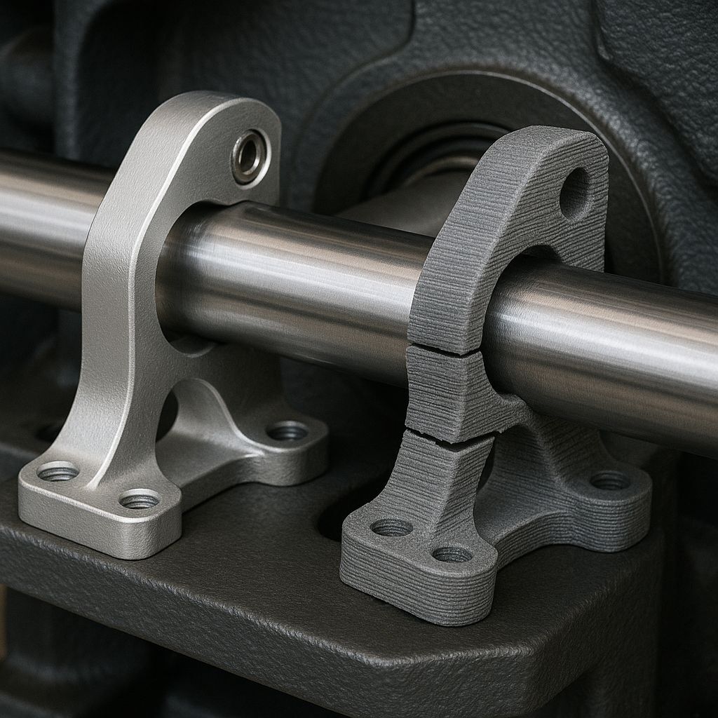
 Polycarbonate part produced by FDM 3D printing: a tough, nearly isotropic material suitable for functional components exposed to loads in multiple directions, such as engine parts.
Isotropic testing:
Tensile (ISO 527), flexural (ISO 178), impact (ISO 179)
Anisotropic testing:
Multi-directional tensile, interlaminar shear, multi-axial fatigue
Typical tolerances:
CNC: ±0.05–0.1 mm
FDM: ±0.2–0.3 mm
Resin: ±0.1–0.15 mm
SLS: ±0.15–0.2 mm
Hybrid materials with isotropic/anisotropic zones
Multi-material printing and thermal post-processing
Selective surface treatments
Integrated topology optimisation
Understanding isotropic vs anisotropic materials is fundamental to:
Optimising design according to real loads
Selecting the most cost- and performance-efficient material
Reducing premature failure risks
Ensuring production quality and reliability
Every project requires a specific analysis of performance, costs, and risks.
At Weerg, we support designers in transforming these choices into real, safe, and high-performance components.
4 min read
Composite materials represent one of the most significant innovations in modern engineering. Thanks to their ability to combine lightness, strength ...
2 min read
Weerg has successfully passed its ISO 9001 certification renewal audit, reaffirming its commitment to excellence in manufacturing processes and...
4 min read
PTFE (polytetrafluoroethylene) is the chemical name of the material; Teflon is the registered trademark under which Chemours (formerly DuPont)...